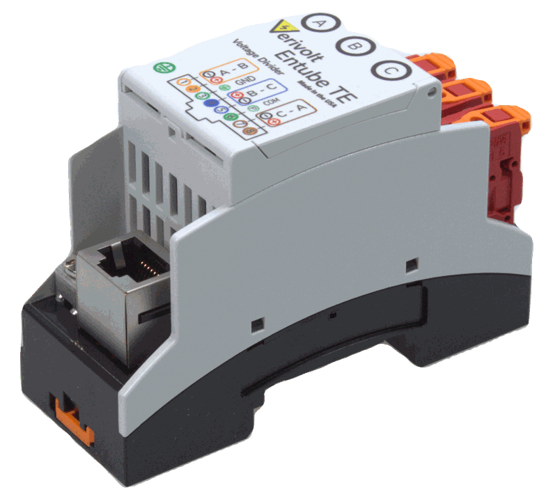
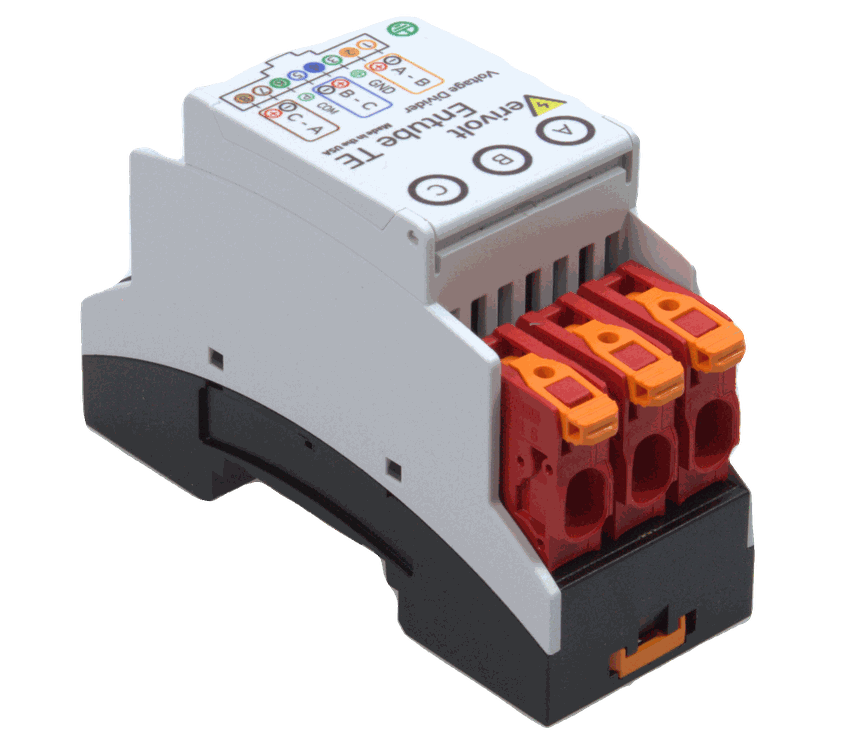
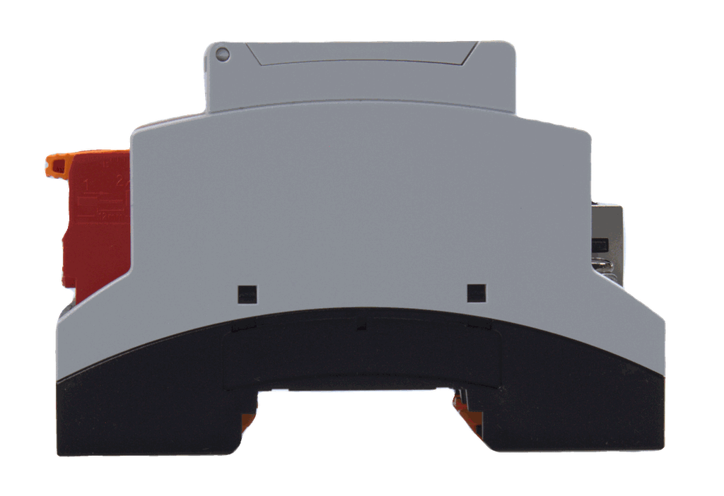
Entube TE
Features±0.2v To ±10v Output Range (Differential Plus Common Mode)
Dc To 50khz Frequency Spectrum Of Operation
Designed For Interfacing With Differential Input Daqs
No Power Supply Needed
Up To ±1500v Input Range On Each Terminal (Line-To-Line And Line-To-Ground)
Documentation

The Entube-TE series is designed for three-phase measurements in a compact form factor without need for power supplies. This product covers the ranges from ±50V to ±1500V, with up to 85kHz bandwidth depending on input range. The high linearity components and smart design deliver better than 0.2% accuracy for properly matched DAQ input impedance.

As the output ranges are ±5V or ±10V this signal can then be processed by most data acquisition devices.
One Entube-TE could replace up to 3 sensors, and only requires one cable for all three signals. This allows for high channel density, while delivering high performance for a low cost.

Because these devices are based on the principles of voltage dividers the primary and secondary ultimately end up sharing the same ground and engineers should be mindful of ground loops or ground faults. They are a great option to measurements of transformers' signals as these signals are already isolated and do not pose a risk of substantial ground shifts.

Principle of Operation
The Entube-TE sensor operates as a differential divider network with an anti-aliasing filter on its output. It senses line-to-line and line-to-ground voltage at its input terminals and generates a scaled down signal at its output. The smart wiring design allows users to easily configure the system as a phase-to-phase voltages for Delta, or phase-to-ground for Wye just by selecting differential or single ended as the DAQ measuring configuration.

Is the Entube TE the right instrument for my application?
As the Entube TE at its core is based on the voltage division principle it has the advantages and limitations intrinsic to voltage dividers. It will work best when connected close to a high input impedance DAQ as it will not be subject to distortions caused by the Data Acquisition Input Impedance as well as wiring plus DAQ Capacitance.

High Input Impedance
Verivolt Entube TE devices have a high input impedance to reduce the unwanted effects of adding a load to a source. Also, the high input impedance increases device safety. The typical current draw of these devices is tens to hundreds of micro Amps depending on model.
For an accurate determination of the impedance, please refer to the specsheet as the input impedance is dependent on the input range of the device.

Surge Resistance
The Entube TE devices are designed to survive and protect other equipment against harmful voltage surges. These depend on the duration but can go as high as 20x the rated measurement range (up to 5kV) for up to 5 microseconds without incurring any damage. Although Entube devices will continue to scale the outputs according to the input, the relatively high output impedance protects the connected DAQ as it makes it very had to draw any damaging currents.
Verivolt text and image block
Verivolt image and text block

Better Connectivity means Improved Performance & Cost
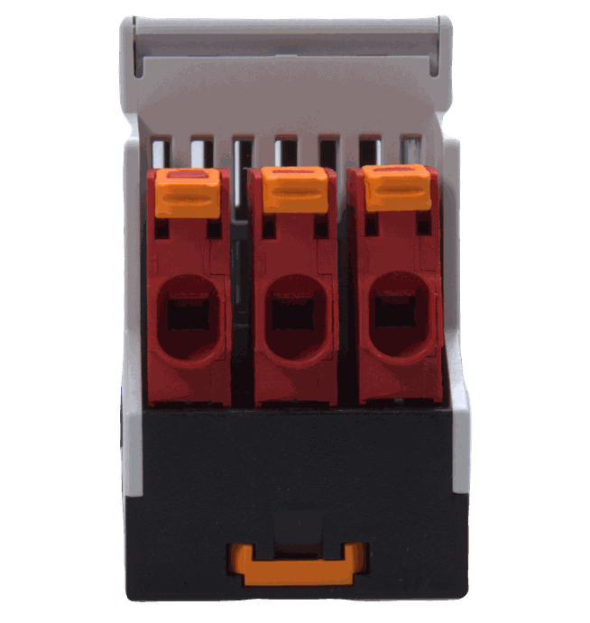
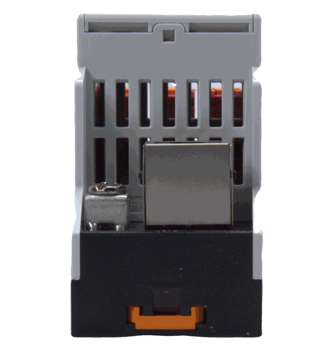
The Entube TE features three spring cage input connectors at the input (one for each phase) and one RJ45 connector at its output for:
Lower installation costs - RJ45 is an industry standard the STP cables are low cost. Also, the simple mating principle saves installation time.
Fewer wiring mistakes - The use of standard cables with connectors reduces the chance of accidental miswiring.
Higher performance - STP cables are twisted and each pair is shielded. This increases immunity to the environment as well as crosstalk.

Customizable Design
Verivolt Entube devices are highly configurable and can have some of their main characteristics customized to satisfy specific applications. Special input impedance, low pass filter, special calibration at specific set point, etc. Please contact us with your special requests and we will do our best to meet your requirements.
